CORE_COMPETENCE
Product_Leaders
index_more
index_more_content
info_item01
info_item_content01
info_item02
info_item_content02
info_item03
info_item_content03
info_item04
info_item_content04
NEWS
NEWS
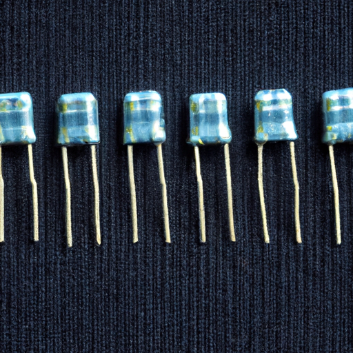
S6008L Resistors highlighting the core functional technology articles and application development cases of Resistors that are effective.
Overview of S6008L Resistors and Their Applications
The S6008L resistors are a specific type of resistor that can be utilized in various electronic applications. While detailed articles or case studies specifically on the S6008L may not be readily available, we can explore the core functional technology of resistors in general and highlight effective application development cases that demonstrate their utility.
Core Functional Technology of Resistors
1. **Basic Functionality**: Resistors are passive components that limit the flow of electric current in a circuit. They are essential for controlling voltage and current levels, ensuring that electronic devices operate within safe parameters.
2. **Types of Resistors**:
- **Fixed Resistors**: These have a constant resistance value and are widely used in circuits for current limiting and voltage division.
- **Variable Resistors**: Potentiometers and rheostats allow for adjustable resistance, making them useful in applications like volume controls and tuning circuits.
- **Specialty Resistors**: Thermistors and photoresistors are sensitive to temperature and light, respectively, and are used in specific applications like temperature sensing and light detection.
3. **Material Composition**: The performance of resistors is influenced by their material composition. Common materials include:
- **Carbon Composition**: Good for general-purpose applications.
- **Metal Film**: Offers better stability and precision.
- **Wire-Wound**: Suitable for high-power applications due to their ability to handle higher currents.
4. **Power Rating**: Resistors are rated for the maximum power they can dissipate, typically measured in watts (W). This rating is crucial for preventing overheating and ensuring reliability in circuit designs.
5. **Tolerance**: This indicates the allowable variation from the stated resistance value, expressed as a percentage. Lower tolerance values indicate higher precision, which is critical in sensitive applications.
6. **Temperature Coefficient**: This parameter measures how resistance changes with temperature, which is vital for applications requiring stable performance across varying environmental conditions.
Application Development Cases
1. **Voltage Divider Circuits**: Resistors are integral in voltage divider circuits, which are used to create reference voltages. For instance, in sensor applications, resistors can scale down voltage levels to match the input range of microcontrollers, ensuring accurate readings.
2. **Current Limiting in LED Circuits**: Resistors are essential for limiting the current flowing through LEDs, preventing damage and ensuring optimal brightness. The selection of the appropriate resistor value is critical for achieving the desired current and performance.
3. **Signal Conditioning**: In analog signal processing, resistors are used in filters and amplifiers to shape and condition signals. For example, in audio applications, resistors can be part of low-pass or high-pass filters, managing frequency response and improving sound quality.
4. **Pull-Up and Pull-Down Resistors**: In digital circuits, pull-up and pull-down resistors ensure that inputs to logic gates are at defined logic levels when no active devices are driving the inputs. This is essential for preventing floating inputs and ensuring reliable operation.
5. **Temperature Sensing with Thermistors**: Thermistors, a type of resistor, are widely used in temperature sensing applications. They change resistance with temperature, allowing for precise temperature measurements in HVAC systems, automotive applications, and consumer electronics.
6. **Power Management**: In power supply circuits, resistors are used for load balancing and creating voltage references. They play a crucial role in ensuring the stable operation of power management integrated circuits (ICs), which are essential for efficient energy use in electronic devices.
Conclusion
Resistors, including specific types like the S6008L, are fundamental components in electronic design, serving various roles from current limiting to signal conditioning. Their effectiveness in applications is determined by their specifications, including resistance value, power rating, and tolerance. Understanding these core technologies and their applications can lead to more efficient and reliable electronic designs. For specific articles or case studies, consulting technical journals, manufacturer datasheets, or industry publications focused on electronic components and their applications would be beneficial.
2025-04-12
0
What are the product characteristics of capacitor wiring diagram?
What are the Product Characteristics of Capacitor Wiring Diagrams?
I. Introduction
A. Definition of Capacitor Wiring Diagrams
Capacitor wiring diagrams are visual representations that illustrate how capacitors are connected within an electrical circuit. These diagrams serve as essential tools for engineers, technicians, and hobbyists, providing a clear understanding of the circuit's layout and functionality. They depict the arrangement of capacitors, their connections to other components, and the overall flow of electrical current.
B. Importance of Understanding Capacitor Wiring Diagrams
Understanding capacitor wiring diagrams is crucial for anyone involved in electrical engineering or electronics. These diagrams not only help in the design and troubleshooting of circuits but also ensure that components are connected correctly to avoid malfunctions or damage. A well-constructed wiring diagram can save time and resources, making it an invaluable asset in both educational and professional settings.
C. Overview of the Article
This article will explore the product characteristics of capacitor wiring diagrams, including their clarity, accuracy, completeness, standardization, and scalability. We will also discuss the basics of capacitors, the purpose of wiring diagrams, common elements found in these diagrams, practical applications, and best practices for creating and interpreting them.
II. Basics of Capacitors
A. Definition and Function of Capacitors
Capacitors are passive electronic components that store and release electrical energy in a circuit. They consist of two conductive plates separated by an insulating material known as a dielectric. When voltage is applied, an electric field forms between the plates, allowing the capacitor to store energy. Capacitors play a vital role in various applications, including filtering, timing, and energy storage.
B. Types of Capacitors
1. **Electrolytic Capacitors**: These capacitors are polarized and typically used for high-capacity applications. They are commonly found in power supply circuits.
2. **Ceramic Capacitors**: Known for their stability and reliability, ceramic capacitors are often used in high-frequency applications and are non-polarized.
3. **Film Capacitors**: These capacitors use a thin plastic film as the dielectric and are known for their low loss and high stability, making them suitable for audio and RF applications.
4. **Tantalum Capacitors**: Tantalum capacitors are also polarized and are known for their small size and high capacitance values, often used in compact electronic devices.
C. Applications of Capacitors in Circuits
Capacitors are used in a wide range of applications, including power supply filtering, signal coupling and decoupling, timing circuits, and energy storage in renewable energy systems. Their ability to store and release energy makes them essential in both analog and digital circuits.
III. Understanding Wiring Diagrams
A. Definition of Wiring Diagrams
Wiring diagrams are graphical representations that show the connections and layout of electrical components in a circuit. They provide a visual guide for assembling, troubleshooting, and maintaining electrical systems.
B. Purpose of Wiring Diagrams in Electrical Engineering
The primary purpose of wiring diagrams is to convey information about the electrical connections and relationships between components. They help engineers and technicians understand how a circuit operates, identify potential issues, and ensure that components are connected correctly.
C. Components of a Wiring Diagram
1. **Symbols and Notations**: Wiring diagrams use standardized symbols to represent different electrical components, such as resistors, capacitors, and switches.
2. **Lines and Connections**: Lines in a wiring diagram indicate electrical connections between components. Solid lines typically represent conductive paths, while dashed lines may indicate non-conductive connections.
3. **Labels and Annotations**: Diagrams often include labels and annotations to provide additional information about component values, specifications, and connection points.
IV. Product Characteristics of Capacitor Wiring Diagrams
A. Clarity and Readability
1. **Importance of Clear Symbols**: Clear and recognizable symbols are essential for effective communication in wiring diagrams. Using standardized symbols helps ensure that anyone reading the diagram can easily understand the components and their functions.
2. **Use of Color Coding**: Color coding can enhance the readability of wiring diagrams by differentiating between various types of connections and components. For example, using different colors for positive and negative connections can help prevent errors during assembly.
B. Accuracy and Precision
1. **Importance of Correct Connections**: Accurate wiring diagrams are critical for ensuring that components are connected correctly. Incorrect connections can lead to circuit malfunctions, damage to components, or even safety hazards.
2. **Avoiding Common Errors**: A well-designed wiring diagram minimizes the risk of common errors, such as mislabeling components or omitting connections. This accuracy is vital for both novice and experienced engineers.
C. Completeness
1. **Inclusion of All Necessary Components**: A complete wiring diagram includes all components necessary for the circuit to function as intended. This includes capacitors, resistors, inductors, and any other relevant components.
2. **Detailed Annotations**: Detailed annotations provide additional context and information about the components and their functions, helping users understand the circuit's operation.
D. Standardization
1. **Adherence to Industry Standards**: Standardized wiring diagrams follow established conventions and guidelines, making them easier to read and understand across different industries and applications.
2. **Benefits of Standardized Diagrams**: Standardization promotes consistency and reduces confusion, allowing engineers and technicians to work more efficiently and effectively.
E. Scalability
1. **Adaptability to Different Circuit Sizes**: Wiring diagrams should be scalable, allowing them to be adapted for circuits of varying sizes and complexities. This flexibility is essential for both small projects and large industrial systems.
2. **Modular Design Considerations**: Modular designs enable the easy addition or removal of components, making it simpler to modify circuits as needed.
V. Common Elements in Capacitor Wiring Diagrams
A. Capacitor Symbols
Capacitor symbols are standardized representations used in wiring diagrams to indicate the presence of capacitors. These symbols vary depending on the type of capacitor, such as polarized or non-polarized.
B. Connection Types
1. **Series vs. Parallel Connections**: Wiring diagrams must clearly indicate whether capacitors are connected in series or parallel, as this affects the overall capacitance and behavior of the circuit.
2. **Grounding and Reference Points**: Grounding symbols and reference points are essential for establishing a common return path for electrical current, ensuring the circuit operates safely and effectively.
C. Additional Components
1. **Resistors**: Resistors are often included in capacitor wiring diagrams to illustrate their role in controlling current flow and voltage levels.
2. **Inductors**: Inductors may also be represented in wiring diagrams, particularly in circuits where capacitors and inductors work together, such as in filters and oscillators.
3. **Switches**: Switches are crucial for controlling the flow of electricity in a circuit, and their representation in wiring diagrams helps clarify how the circuit can be activated or deactivated.
VI. Practical Applications of Capacitor Wiring Diagrams
A. In Consumer Electronics
Capacitor wiring diagrams are widely used in consumer electronics, such as smartphones, televisions, and audio equipment. They help engineers design circuits that optimize performance and reliability.
B. In Industrial Applications
In industrial settings, capacitor wiring diagrams are essential for designing and maintaining complex machinery and control systems. They ensure that components are connected correctly for safe and efficient operation.
C. In Renewable Energy Systems
Capacitors play a vital role in renewable energy systems, such as solar inverters and wind turbines. Wiring diagrams help engineers design circuits that maximize energy efficiency and reliability.
D. In Automotive Engineering
In automotive engineering, capacitor wiring diagrams are used to design and troubleshoot electrical systems in vehicles, including power distribution, lighting, and infotainment systems.
VII. Best Practices for Creating and Reading Capacitor Wiring Diagrams
A. Tips for Designing Effective Diagrams
1. Use standardized symbols and notations to enhance clarity.
2. Incorporate color coding to differentiate between connections and components.
3. Ensure all components are labeled and annotated for easy reference.
B. Techniques for Reading and Interpreting Diagrams
1. Familiarize yourself with common symbols and notations.
2. Follow the flow of the diagram to understand how components are connected.
3. Pay attention to annotations for additional context and information.
C. Tools and Software for Diagram Creation
Various software tools are available for creating wiring diagrams, including AutoCAD, Microsoft Visio, and specialized circuit design software. These tools can streamline the design process and ensure accuracy.
VIII. Conclusion
A. Recap of Key Points
In summary, capacitor wiring diagrams are essential tools for understanding and designing electrical circuits. Their product characteristics, including clarity, accuracy, completeness, standardization, and scalability, play a crucial role in ensuring effective communication and functionality.
B. The Importance of Mastering Capacitor Wiring Diagrams
Mastering capacitor wiring diagrams is vital for anyone involved in electrical engineering or electronics. A solid understanding of these diagrams can lead to improved circuit design, troubleshooting, and overall efficiency.
C. Encouragement for Further Learning and Exploration
As technology continues to evolve, the importance of understanding capacitor wiring diagrams will only grow. We encourage readers to explore further resources, engage in hands-on projects, and continue learning about this essential aspect of electrical engineering.
IX. References
A. Suggested Reading Materials
1. "The Art of Electronics" by Paul Horowitz and Winfield Hill
2. "Electrical Engineering 101" by Darren Ashby
B. Online Resources and Tools
1. Electronics tutorials and forums
2. Circuit simulation software
C. Industry Standards and Guidelines
1. National Electrical Code (NEC)
2. International Electrotechnical Commission (IEC) standards
By understanding the product characteristics of capacitor wiring diagrams, you can enhance your skills in electrical engineering and electronics, paving the way for successful projects and innovations.
2025-03-15
3